Hull Detailing 2 (after Hull Assembly)
Continuing with the hull detailing started in section 2, there was lots more to do AFTER the hull was assembled:
- Hull rippling (“oil canning”)
- Welds
- Drip channels
- Anchor alcove
- Saddletank hatch covers
- Hull casing double-row rivets ("doublers")
- Bow bullnose
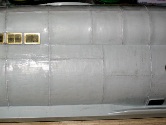
Hull Rippling (“Oil Canning”)
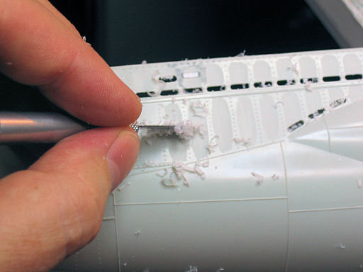
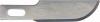
Following in the footsteps of Wink Grisé’s build of U‑557, I decided to mimic the outer hull “oil canning” that occurs on the hull surface. Much of the effect is made by scraping with a sharp X-Acto #10 General Purpose blade. After I have finished all scraping, I will finish up with fine sanding.
If you decided to undertake this effect, be warned! The work is tedious, and you will produce A LOT of plastic shavings. On top of that, after a long period of scraping with the hobby knife, I found that one part of one fingertip had gone numb... and lasted for a few days! (Repetitive stress injury most likely.) Always use a sharp blade, and plan to go through a few of them (I went through 8~10 blades on one half of the hull.)
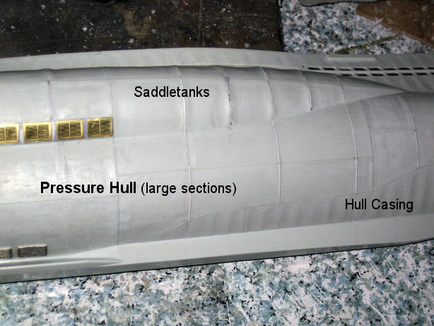
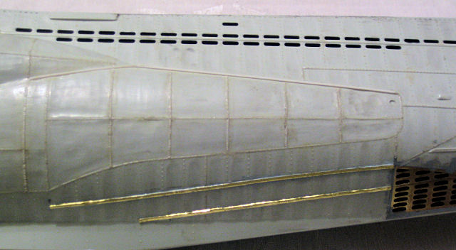
External Hull Casing
The rows of rivets indicate the locations of the internal ribs of the hull casing. The oil canning effect was made primarly by shallow scraping of the areas between the ribs with a sharp X-Acto #10 General Purpose blade.

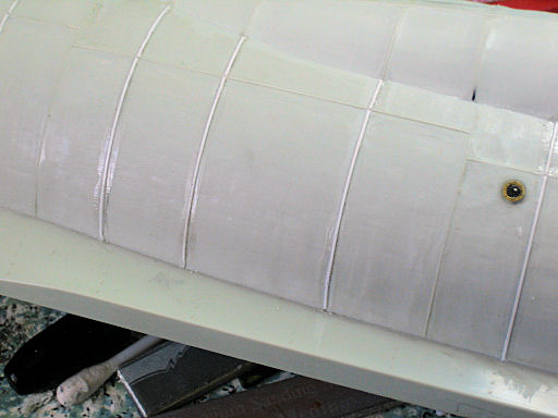
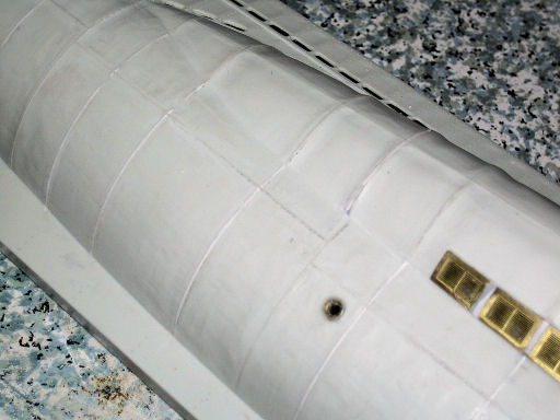
Saddletanks
The weld beads (stock kit beads & additional beads) indicate the locations of the internal ribs of the saddletanks. The areas between the ribs were scraped and sanded to make a depression effect and make the ribbed areas more prominent.

Pressure Hull
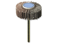
The remaining areas of the visible pressure hull – those areas bordered by weld beads, not rivet rows – were textured much like the saddletanks, with additional random creases added. To speed up the process, I used a Dremel flapwheel sander (120 grit) to rough the surface; great care must be taken not to remove any other surface detail.
Welds
For an in-depth look at the tool & technique I used to make the weld beads, see HERE.
The welds on the stock kit hull are uniform in shape and size. To make them more realistic, first I flattened them by scraping with a hobby knife, and then I added texturing with my homemade weld bead tool & technique.
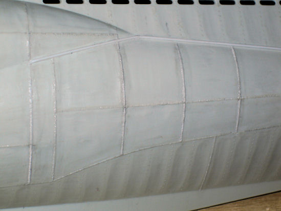
The amount of weld beads on the kit is minimal, so to enhance that I laid out the locations of additional weld beads. Since styrene rod would be the wrong shape and height, I selected 0.010 x 0.020" flat strip styrene. I used Tenax-7R liquid cement to adhere the strip styrene to the kit hull, let them dry, and then sanded and textured them to resemble real weld beads.
For an in-depth look at the tool & technique I used to make the weld beads, see HERE.
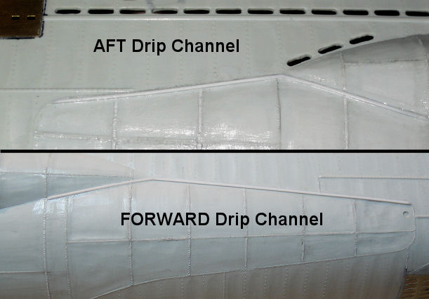
Drip Channels
I added bow and stern drip channels at the forward and rear ends of the saddletanks. These were made with 0.030" quarter-round styrene. They follow the curve of the saddletank end and then along the weld lines.
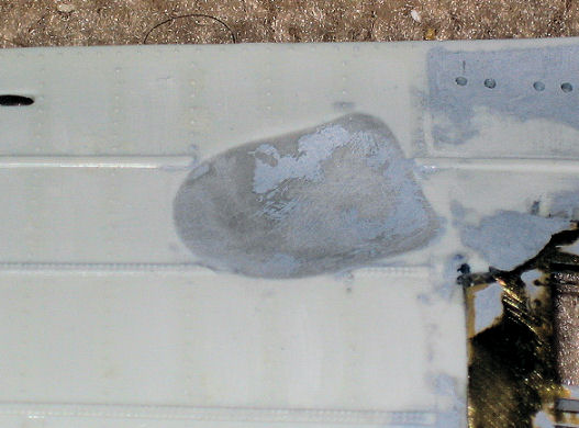
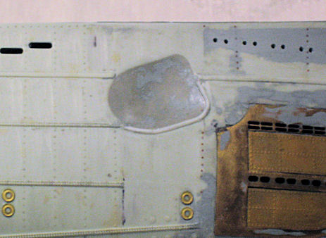
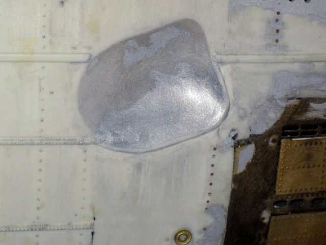
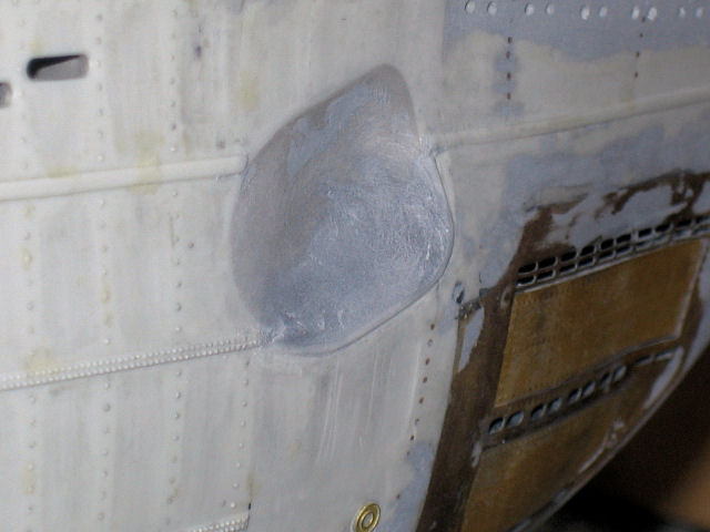
Anchor Alcove
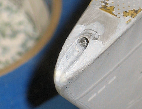
The alcove for the bow anchor is a little bit too deep and square-edged, so I used Kraftmark™ ProCreate epoxy putty (probably the best epoxy putty I've ever used) to fill in the anchor alcove a bit and give it softer edges where it meets the outer hull.
A thin lip was added to the lower edge of the anchor cavity using a piece of half-round 0.040" strip styrene.
Tamiya Putty was then used to fill in and smooth the bottom edge of the alcove where it met tne lower lip.
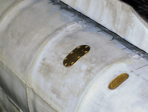
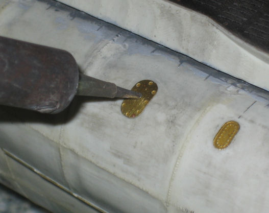
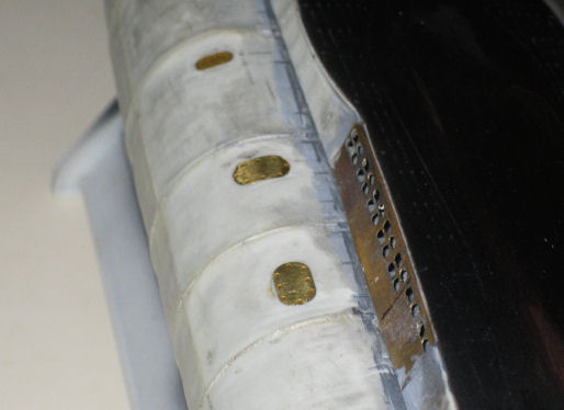
Saddletank Hatch Covers
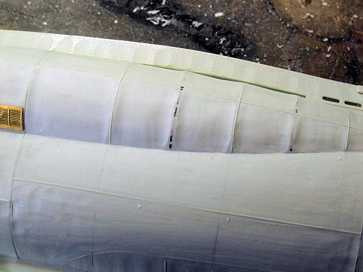
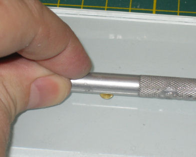
I used the oval-shaped saddletank hatch covers included in the Modelbrass PE set.
First I pre-curved the hatch cover by rolling a hobby knife handle over it. Once the hatch cover had the proper curve, I glued it temporarily in place on the saddletank using CA glue. Using a 25W soldering iron with a fine tip I heated the brass hatch cover until it softened the plastic underneath, then I gently pushed the heated hatch cover into the plastic until it was flush. A bit of sanding was required to smooth all edges.
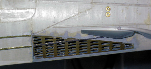
Hull Casing Double-rivet Rows (‘Doublers’)
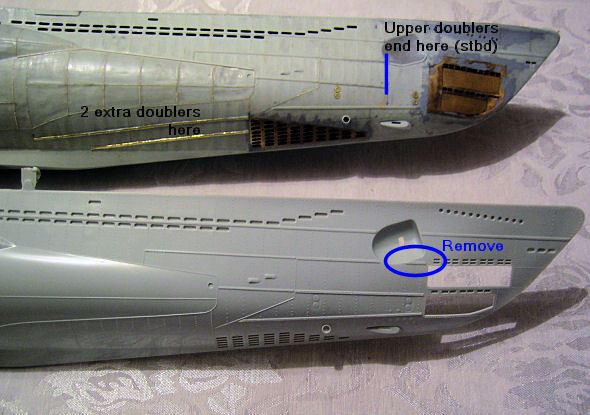
The narrow double-rivet rows (a.k.a. ‘doublers’) are strenghtening strips on the hull casing. The doublers on the kit hull need some correction.
On the starboard bow, the two top doublers end in the same place as shown, and the small doubler ahead of the anchor cavity must be removed.
On the bottom of the port and starboard bow, there are two ‘doublers’ that are missing completely.
To make the additional two doublers, I first marked the positions and then glued pieces of strip styrene 0.010x0.040" into place.
To make the raised double rivet rows I used a ponce wheel to indent double rivet rows into a piece of super-thin 0.001" brass shim stock, cut the brass shim into a 0.040" wide strip, and used CA to glue it onto the pieces of strip styrene.
After the lower doubler reaches the rear edge of the bow lower vents, a single-row of rivets extends forward through a narrow gap in the bow lower vents... all the way to the bow plane pivot. I used a single rivet row from the Eduard S-100 Schnellboot Flak38 PE set (53033).
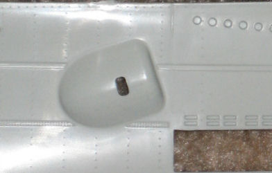
Bow Bullnose *Updated*
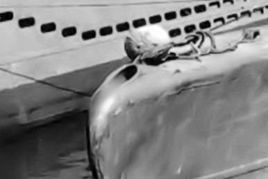
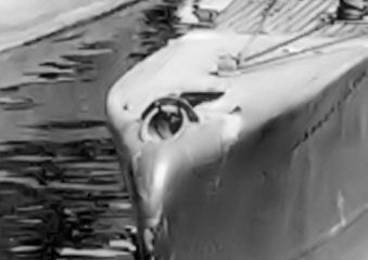
In the Revell kit, the molded bullnose detail (on the top deck near the tip of the bow) is too small. After finding some very good reference photos, I decided to reshape the bullnose... and it took 2 attempts to get it the way I wanted.
The bullnose is comprised of two parts: the inlet and the channel. The inlet is a round hole in the upper bow deck, and it is angled downward at a shallow angle into the hull. The channel is a shallow, sculpted groove ahead of the inlet; the channels of some boats are more pronounced than others. The pictures below show differently-shaped bullnoses of various VIIC and VIIC/41 U-boats.

(Wiper, S. 2004. Warship Pictorial #27: Kriegsmarine Type VII U-boats (p. 34, 68) . Tucson, AZ: Classic Warships Publishing.)
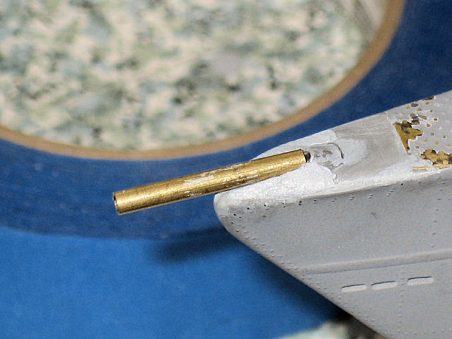
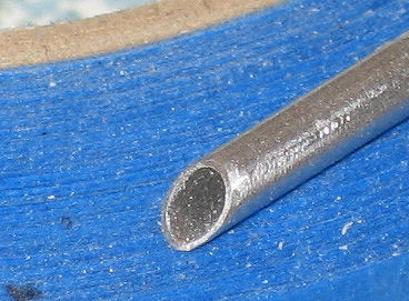
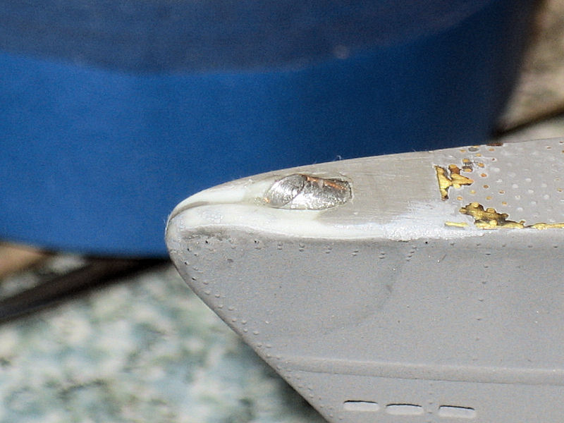
I started by sanding down the molded-on bullnose detail on the kit deck. For the new inlet I used 1/8" aluminum tubing, and filed a 30–45° angle at the leading edge.
To insert the inlet tube through the top deck, I had to drill an 1/8" hole at a shallow angle (approximately 20–30°). (In hindsight I could have made the angle even shallower.) I then used a round jewellers file to make a shallow groove in the hull, filing down approximately 1mm. Inserting the inlet tube into the hull, I pushed in the tube until its lower edge was even with the bottom of the groove. I used medium-thick CA to glue the tube in place, and then used Tamiya Putty to fill the gaps.
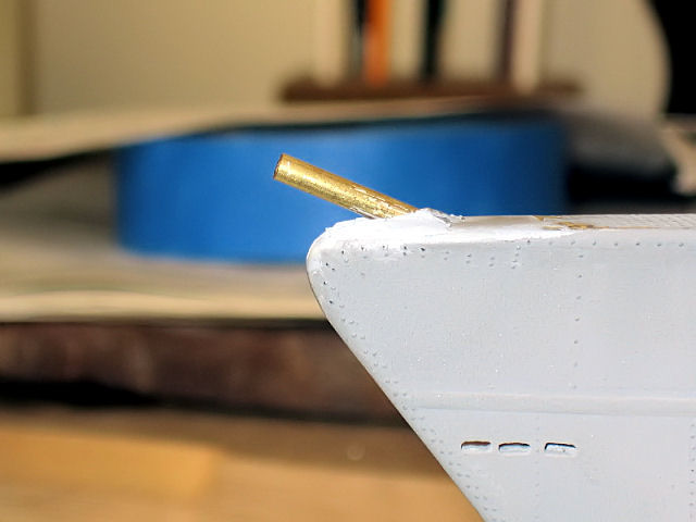
To properly sculpt the channel, I started by further filing the hull groove I had already started until it was 80% the correct shape. Then I took a smaller piece of 3/32" brass tubing — the next size smaller than the 1/8" inlet tube — and lay it in the groove. I then used Tamiya Putty to build up the sides of the channel, using the brass tubing to provide a form for the putty to go around. After I removed the brass tubing, the channel had the proper rough shape with built-up sides. All that remained was to file/sand the putty sides into the proper shape.