Hull Detailing 1 (before Hull Assembly)
I knew that the most challenging and time-consuming aspect of my U‑673 build would be the detailing of the hull.
Hull detailing in my U‑625 build was mostly limited to some PE detailing, so for U‑673 I wanted to put in a lot more time and energy into superdetailing and correcting the kit hull. I planned to do some major reconstruction (flood vent correction and bow door replacement), create different hull effects (rippling or “oil canning”), and of course add PE detail as well. This would be a bigger and more complicated phase than I had originally thought, and would involve a lot of cutting, PE bending, grafting, scraping, puttying and sanding... not to mention leaps of faith as I cut out large sections of a perfectly good kit hull.
Ultimately though, most of the “major” tasks (such as cheek replacement) turned out to be not as daunting as I had imagined... though a fair bit of time is involved.
Here is the hull detailing that was done BEFORE the hull was assembled:
- Resources
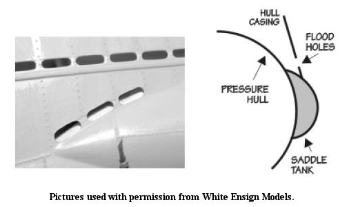
- Opening up the flooding holes
- Saddletank vents
- Lower flooding vents
- Bow “cheek” pieces
- Central vent holes (small) & diesel exhaust outlets
- Bow flood holes (12 round holes)
- Bow flood slots (3 oval slots)
- Miscellaneous large flooding holes
- Saddletank inner curve
Resources
Drawing upon a few resources and products, I selected the following sets to detail the hull:
- Saddletank vents
Yankee Modelworks PE set for VIIC (YKM-7202) - Lower flooding vents, bow & stern
Modelbrass PE Set (WM7201) - Bow cheek plates, diesel exhaust vents, miscellaneous upper hull holes
U-Brass Type VII U-boat Flood, Drain and Vent Holes (PE7232)
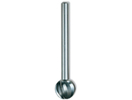
Opening Up the Flooding Holes
The first order of business was to open up all of the flooding holes in the kit hull. To do this I carefully used a Dremel tool with a #114 High-speed Cutter (round head) to thin out the plastic from behind, and then I cut out the holes with a sharp #11 Xacto knife. A bit of beveling on the inside of the holes would create the illusion of scale thickness of the outer hull casing.
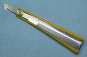
For the long flooding channels atop the saddletanks – which I opened up AFTER I had done the "oil canning" of the hull – I used an Olfa plastic scriber to scribe most of the way through the plastic, and then used a sharp #11 Xacto blade to slice through the rest. The results are much cleaner, straighter cuts than what you would get trying to grind through the plastic with a Dremel bit. It also leaves very nice clean edges along the top of the saddletank curves to which I would add my extensions curving inside... more on this in chapter 4 “Saddletanks.”
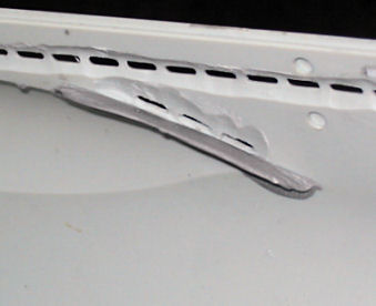
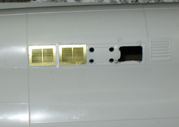
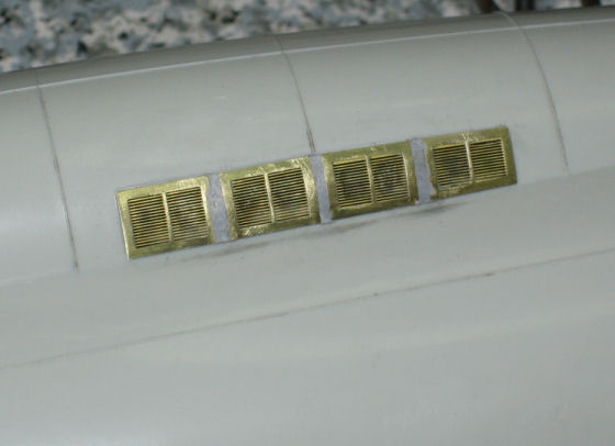
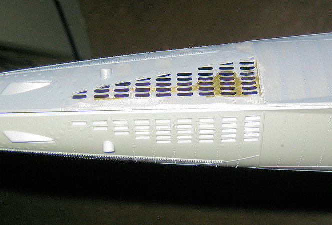
Saddletank Vents
I added PE saddletank vents from the Yankee Modelworks PE set. I first cut away the plastic behind the vents so that there would appear to be open space behind them; this took careful measurement and cutting. I also chamfered the inside edges of the holes. Narrow strips of thin styrene were added as spacers between the PE vent plates.
Yankee Modelworks produces the only PE set on the market that contains these particular saddletank vents, and the set contains very many other fine details.
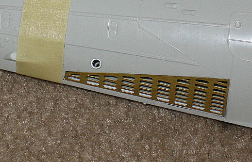
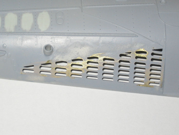
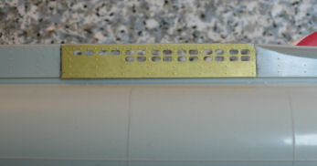
Lower Flooding Vents
In order to replicate the proper lower flooding vent patterns at the bow and stern, I grafted Modelbrass PE lower flood vent plates to the kit hull. The Modelbrass PE set is the only set available with these particular flood vents.
Bending the lower bow vent section was fairly easy, as there is very little curvature. However, the stern lower vent section has a complex shape... time and patience is required to get it to the right shape and fit the hull.
After bending the PE pieces to the proper shapes, I taped them in location on the plastic hull, and traced their perimeter with a sharp #11 Xacto blade. I then carefully cut away the plastic hull (cutting smaller holes then sanding to exact shape). Once the cutouts were the proper size & shape, I added pieces of thin square 0.015~0.020" styrene to act as "shelves" around the inside edges of the cutouts, so that the PE piece would have better support and also be at the right height to blend properly with the surrounding plastic hull.
Thick CA (gap-filling) glue was used to attach the PE plates to the kit hull, being careful not to clog any of the fine holes. A lot of puttying and sanding was required to blend the edges of the PE pieces into the kit plastic hull.
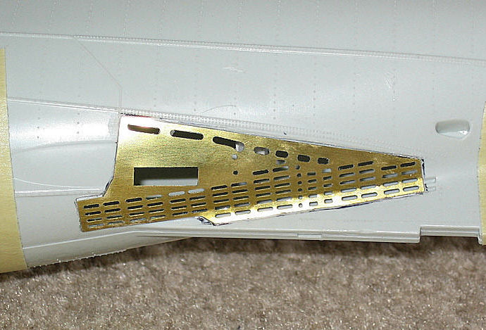
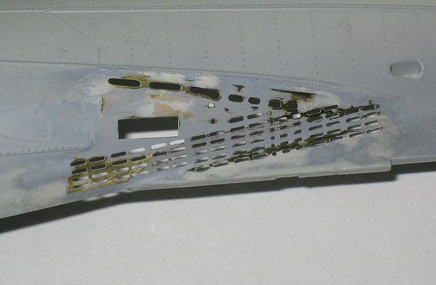
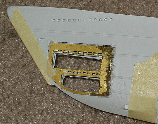
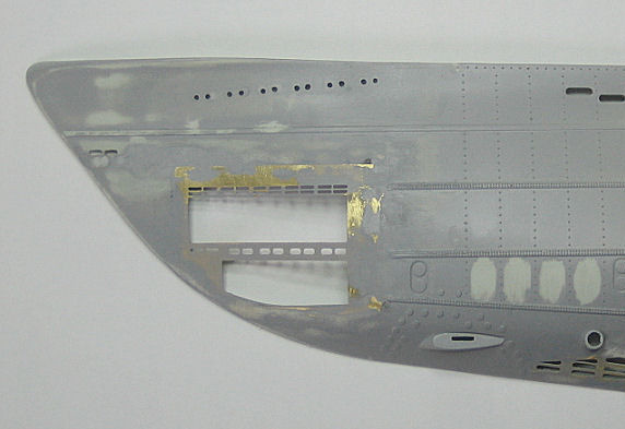
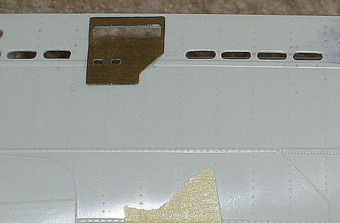
Bow “Cheek” Pieces
Research has revealed that the bow torpedo doors on the Revell kit are too long, and the flooding holes surrounding the doors are also the incorrect size/shape. The U-Brass PE set includes several “cheek” pieces that correct these inaccuracies, for various versions of the VII boats.
Adding the bow cheek pieces was definitely one of those “leap of faith” aspects of this build. After selecting the proper cheek piece for U-673, I bent it to shape and grafted it into the hull using the same process as the lower flooding vent plates... cutting away just enough of the plastic hull to give room for the plates, while leaving as much plastic hull as possible to support the edges.
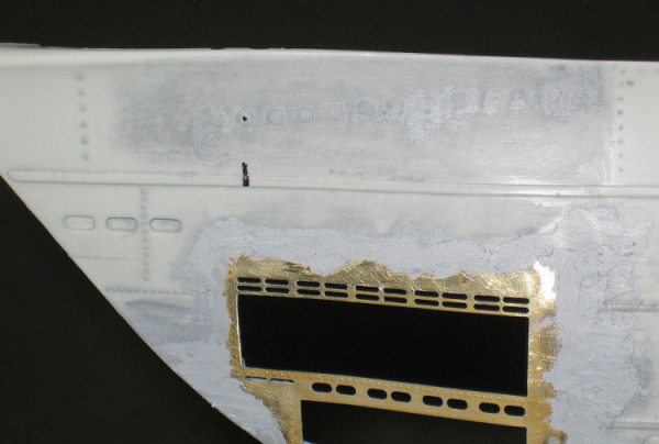
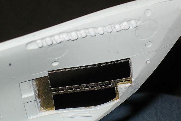
Thick CA (gap-filling) glue was used to attach the PE cheek piece to the kit hull, and then a lot of puttying and sanding was required to blend the edges of the PE cheek piece into the kit plastic hull.
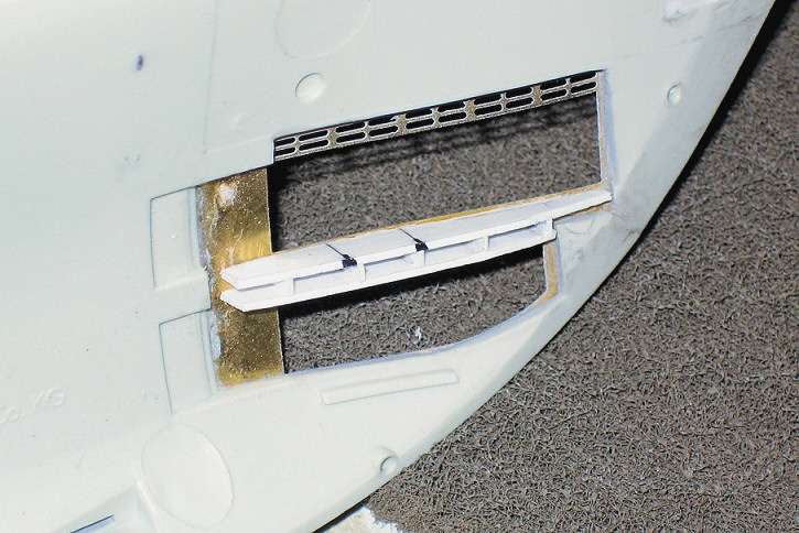
For the area behind the cheek’s middle flood holes (between the upper and lower torpedo doors), I made a simple assembly to simulate the internal structures. The upper and lower horizontal plates are made from 0.020" sheet styrene cut to shape, and they are separated by thin vertical ribs of 0.020"x0.060" styrene. The ribs are aligned with the gaps between the pairs of oval holes in the cheek piece. The completed assembly was glued to the inside of the brass cheek piece with CA glue, making sure to not cover the flooding holes.
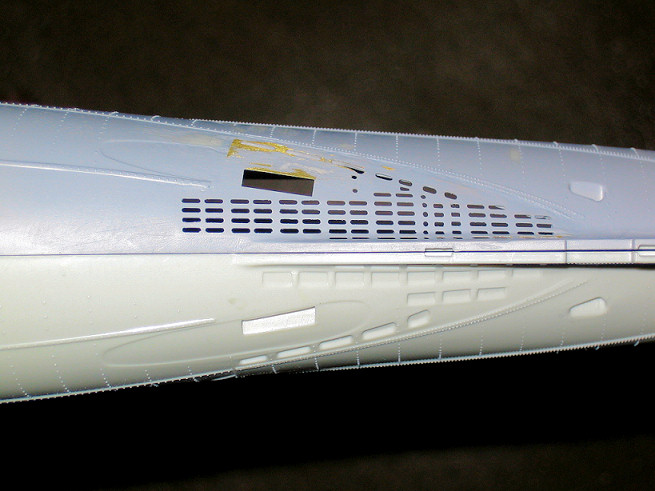
Central Vent Holes (Small) & Diesel Exhaust Outlets
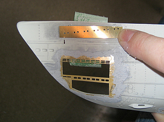
The group of small vent holes on the sides of the upper hull were incorrect for U-673, so I grafted a section from the U-Brass set to the hull. I filed a shallow groove in the plastic so the PE would sit flush, and cut out sections of the kit hole so the holes would not be blocked.
Proper diesel exhaust outlet plates were added to the sides of the hull from the U-Brass PE set.

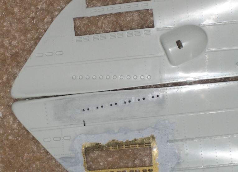
Bow Flood Holes (12 Round Holes)
On the Revell kit, the 12 small round vent holes in the bow are too large and improperly placed. Also, depending on the boat you are modelling, the holes may be either evenly spaced or paired. I used the appropriate template from the U-brass PE set to drill new paired holes.
First I filled the stock holes. Instead of simply puttying them (which I knew would not work well), I drilled out the holes, press fit pieces of 0.080" styrene rod, and then puttied and sanded the outside. After that, I taped the proper PE template in place, aligning the #1 hole in the template with the stock #2 hole. Using the appropriate sized micro drill, I then drilled the 12 paired holes.
The resulting paired holes are now to scale and in the proper locations.
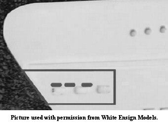
Bow Flood Slots (3 Oval Slots)
On the Revell kit, the 3 small oval slots in the bow are too large, improperly placed, and have the incorrect number on the starboard side. On the VIIC the port side has 3 slots while the starboard side has only 2 slots (forward). The U-brass PE set contains a template to create the proper slots.
Like with the bow flood holes, I drilled out the slots, filled them with 0.080" styrene rod, and then puttied and sanded the outside. After that, I taped the proper PE template in place, drilled holes, and then trimmed and filed the slots to the proper shapes. The resulting slots are now to scale and in the proper locations.
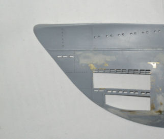
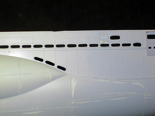
Miscellaneous Large Flooding Holes
To match the proper patterns of large flooding vent holes in the upper hull (stern), I had to fill in some kit holes and cut other holes. When filling the holes I did not use putty by itself, as this would most likely shrink. I filled the holes with styrene and applied medium 'gap-filling' CA to any seams... then used CA accelerator to harden it quickly. (Hardened CA is VERY hard and sands well.)
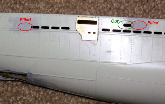
I also cut the 3 flooding holes above the stern ends of the saddletanks; these are not molded into the kit.
Saddletank Inner Curve
With the 3 large flooding holes added to the outer hull above rear edge of the saddletank, looking through those holes you should be able to see the curve of the inner part of the saddletank. To represent this, I used Kraftmark™ ProCreate epoxy putty to create a faux section of the saddletank behind the newly-created flooding holes.